How to Create a Network Architecture Diagram With Examples
Introduction
A network architecture diagram shows how routers, switches, firewalls, and other devices connect within a computer network. The diagram also helps you trace how data travels between network segments and understand how different parts of the infrastructure communicate.
Depending on your requirements, you might need a physical network diagram showing hardware and cable connections, or a logical network diagram showing traffic flow across subnets and VLANs. Knowing what to include and how to organize the connections helps you decide which diagram structure suits your network.
In this guide, we'll explore different diagram structures through practical examples. We'll also walk through how to create a network architecture diagram that accurately represents your infrastructure.
What is a network architecture diagram?
A network architecture diagram is a technical illustration of a computer network's structure and layout. It shows where network devices are placed and how they connect through physical or virtual links. The diagram also identifies network boundaries and communication paths, helping IT teams document existing infrastructure and plan network changes.
A typical network architecture diagram includes five main elements:
- Network devices: Hardware such as routers, switches, firewalls, servers, and load balancers. Wireless access points and connected endpoints may also appear.
- Network connections: Physical cables, wireless links, VPN connections, and virtual network links that connect devices within or across networks.
- Network organization: LANs, WANs, subnets, and VLANs that show how the network is divided into different segments.
- Traffic flow: The paths data follows when moving between devices, applications, servers, and external services.
- Network boundaries: The separation between on-premises infrastructure, cloud environments, and security zones.
A network architecture diagram can be as simple as a small office network or detailed enough to represent an entire enterprise infrastructure. Depending on its purpose, the diagram can focus on physical connections or show how data moves between network segments.
What are the benefits and uses of network architecture diagrams
Network architecture diagrams help IT teams manage network infrastructure more efficiently by making network relationships easier to understand and verify. With an updated diagram, engineers can make informed decisions about network changes and reduce the risk of overlooking dependencies that could affect connectivity or security.
Some of the key benefits and uses of network architecture diagrams include:
- Network planning and design: Visualizing the proposed network helps teams assess infrastructure requirements and compare possible layouts. Engineers can identify missing connections before configuring or installing equipment.
- Troubleshooting network issues: Diagrams help administrators trace communication paths and narrow down where connectivity problems may occur. They can identify possible points of failure without checking every device individually.
- Infrastructure documentation: A network diagram records the existing setup and how different network segments connect. Regular updates keep the documentation useful as devices or configurations change.
- Network security planning: Mapping VLANs, DMZs, and firewall boundaries helps security teams review how traffic moves between protected areas. It also makes unintended access paths easier to identify.
- Improved communication and collaboration: A shared diagram gives engineers and other stakeholders a common reference when discussing network changes. Teams can review proposed connections and identify concerns before implementation.
- Network upgrades and expansion: Diagrams help teams understand how new infrastructure will fit into the existing network. For example, an IT team adding a branch office can use its WAN diagram to identify required connections and security controls before extending the network.
Verizon’s 2025 Data Breach Investigations Report found that vulnerability exploitation was the initial access vector in 20% of breaches. This means teams should clearly mark perimeter devices and VPN connections when reviewing network security.
Types of network architecture diagrams
Network architecture diagrams generally fall into two categories, physical and logical. While both represent the same network infrastructure, the information they capture differs. Physical diagrams help engineers locate and manage network hardware, while logical diagrams focus on understanding connectivity across network segments.
Aspect | Physical Network Diagram | Logical Network Diagram |
Focus | Physical arrangement of equipment and hardware connections. | Network organization and communication paths. |
Components | Routers, switches, firewalls, servers, racks, cables, and ports. | IP address ranges, subnets, VLANs, and routing relationships. |
Connections | Physical cables and links between devices. | VPN connections, routing paths, and communication between subnets. |
Device location | Shows equipment placement within buildings, server rooms, or data centers. | Represents network relationships regardless of physical location. |
Common uses | Equipment installation, cabling documentation, and hardware maintenance. | Routing analysis, access control reviews, and connectivity troubleshooting. |
Uptime Institute’s 2025 Global Data Center Survey found that 14% of respondents attributed their most recent impactful data center outage to network issues. This shows why a diagram should make network paths and dependencies easy to trace when investigating an outage.
Tip: For larger networks, separate physical, logical, and Layer 3 views instead of forcing every connection onto one page. A shared template with consistent link colors, symbols, and a legend helps engineers read diagrams across the team.
What is network topology and its different types
Network topology describes how devices and communication links are arranged within a network. While network architecture covers the overall infrastructure, topology focuses on the connection patterns that determine how devices communicate.
The six common network topology types are bus, star, ring, mesh, tree, and hybrid. Each influences how devices communicate, how failures affect connectivity, and how the network can grow.
1. Bus topology
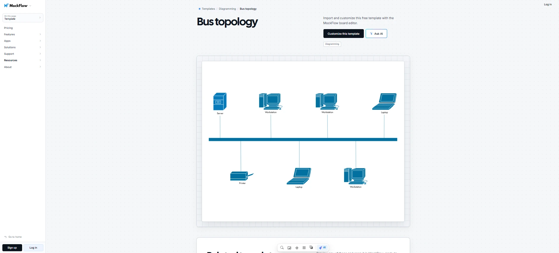
Bus topology connects multiple devices to a single shared backbone. All communication passes through the same transmission medium, creating a linear network arrangement.
When a device sends data, the signal travels along the bus topology backbone to reach its intended destination. A failure in the main cable can disrupt communication across the network. Bus topology is largely associated with older Ethernet networks and certain specialized systems.
MockFlow's Bus Topology Template gives you a starting layout for mapping devices along a shared backbone. You can customize the diagram to document individual connections and identify where a backbone failure could affect connectivity.
Customize this bus topology template
2. Star topology
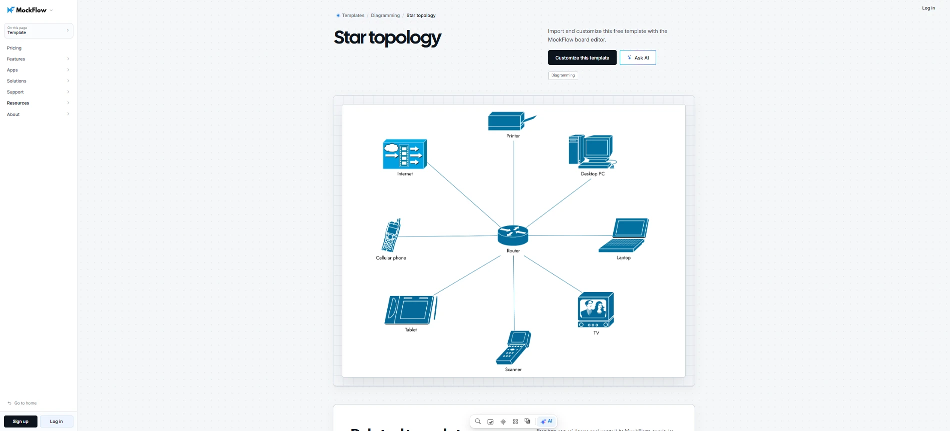
Star topology connects every device to a central networking component, usually a switch. Each device has a dedicated connection to the central switch, which manages communication across the network.
In star topology, if one endpoint or its cable fails, other connected devices can generally continue communicating. However, a failure in the central switch can interrupt connectivity for the entire star connected network.
Star topology is widely used in modern office networks because individual connections are easier to manage and troubleshoot. You can customize MockFlow's Star Topology Template to map devices around a central switch and review the connections each endpoint depends on.
Customize this star topology template
3. Ring topology
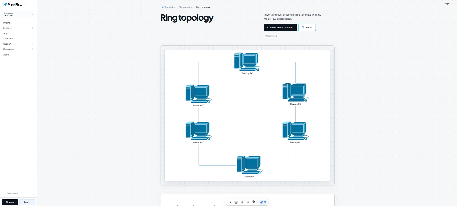
Ring topology connects devices in a closed loop, where each node links to two neighboring nodes. Data travels around the ring through connected devices until it reaches its destination.
In a basic ring, a broken connection can interrupt network communication. Redundant ring designs can provide alternative paths, depending on the networking technology used.
Ring topology remains relevant in certain industrial and specialized network environments. MockFlow's Ring Topology Template can help you illustrate the closed-loop arrangement and examine how devices are linked around the network.
Customize this ring topology template
4. Mesh topology
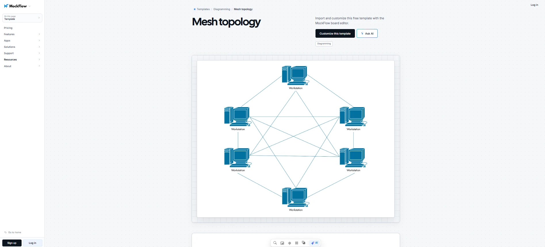
Mesh topology creates multiple connections between network devices, allowing communication through more than one path.
There are two common mesh topology arrangements:
- Full mesh: Every device has a direct connection to every other device.
- Partial mesh: Selected devices have multiple connections, while others connect through fewer paths.
Mesh topology improves network resilience by providing alternative communication paths when a connection fails. However, traffic can only be rerouted if the network supports an available alternative route.
Mesh topology is commonly considered for WAN environments and networks where connection reliability is a priority. With MockFlow's Mesh Topology Template, you can map interconnected devices and customize the links to illustrate redundant paths within your network.
Customize this mesh topology template
5. Tree topology
Tree topology arranges network devices in a hierarchical structure, with higher-level devices branching into lower-level connections.
In an enterprise network, tree topology may consist of a core layer connected to distribution switches. The distribution switches then connect to access switches serving individual departments or buildings.
Tree topology helps organize large networks into manageable layers and makes it easier to expand individual network sections. However, failures in higher-level devices can affect multiple downstream connections, making redundancy important in hierarchical network designs.
6. Hybrid topology
Hybrid topology combines two or more network topology structures within a single infrastructure. For example, an enterprise may use star topology within office LANs and mesh topology for connections between critical network sites.
Hybrid topology allows organizations to choose different connection structures based on the requirements of each network environment. Branch offices might use WAN links to connect with headquarters, while a data center follows a separate topology designed for redundant communication.
Hybrid topology is particularly useful for large enterprise networks that require different connectivity arrangements across locations.
Related Read: Top 8 Architecture Diagram Tools for Collaboration and Design
Network architecture diagram examples and templates
The right network architecture diagram depends on the infrastructure you need to represent and the connections you want to document. Practical examples and templates help you understand how to organize network components and choose the appropriate level of detail.
Let's look at how different network environments can be mapped and what each diagram should capture.
1. Simple network architecture diagram
A simple network architecture diagram represents a small network with a few interconnected devices. It typically shows how an internet connection reaches a router, which connects to a switch that serves computers or a shared server.
This diagram is useful for documenting basic network connectivity or planning small expansions. You can identify device dependencies and determine where additional equipment should connect.
2. Office or home network diagram
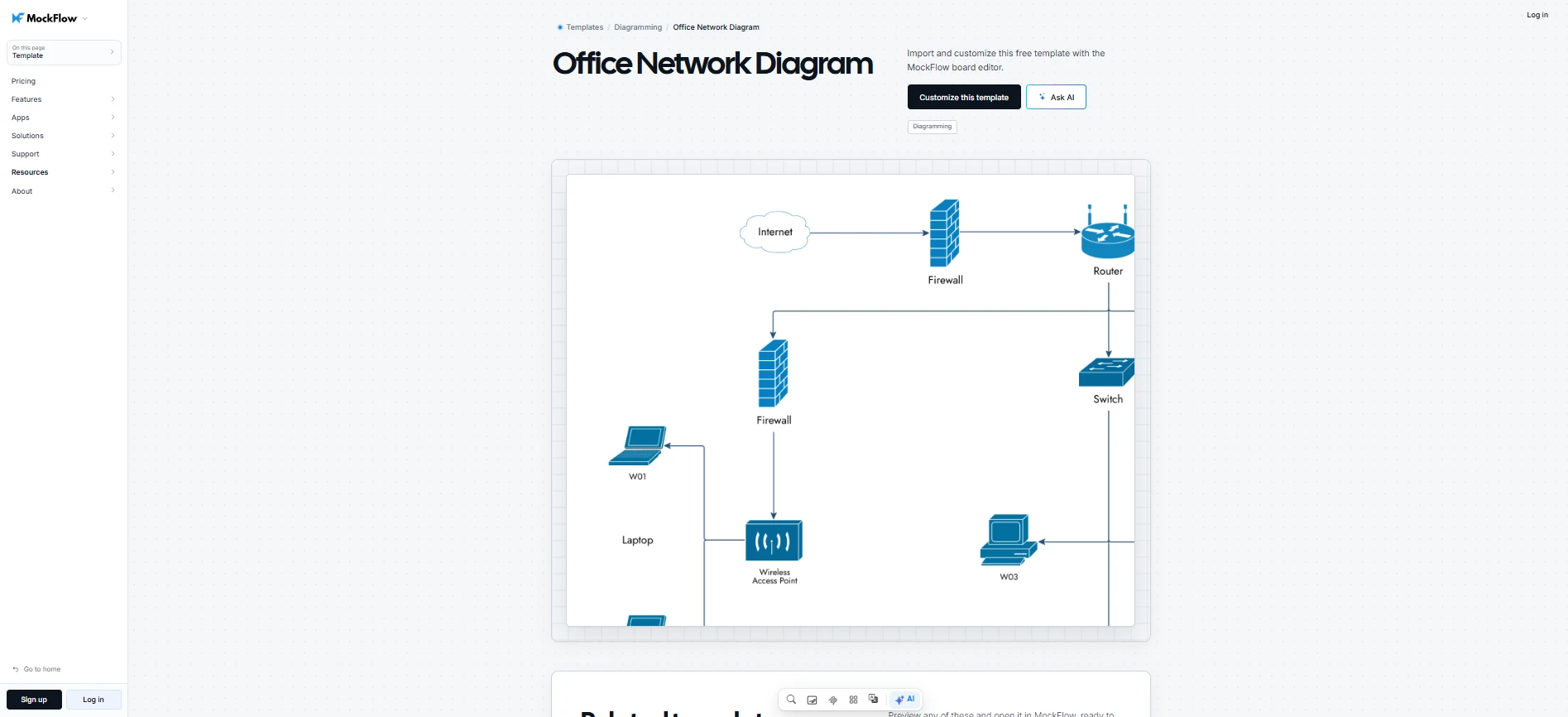
An office or home network diagram shows how wired and Wi-Fi devices connect through an internet gateway, router, switches, and access points. It can also map shared resources such as printers and network storage.
MockFlow's Office Network Diagram Template gives you an editable starting point for documenting this setup and tracing connectivity issues.
Customize this office network diagram template
3. Physical and logical network diagram examples
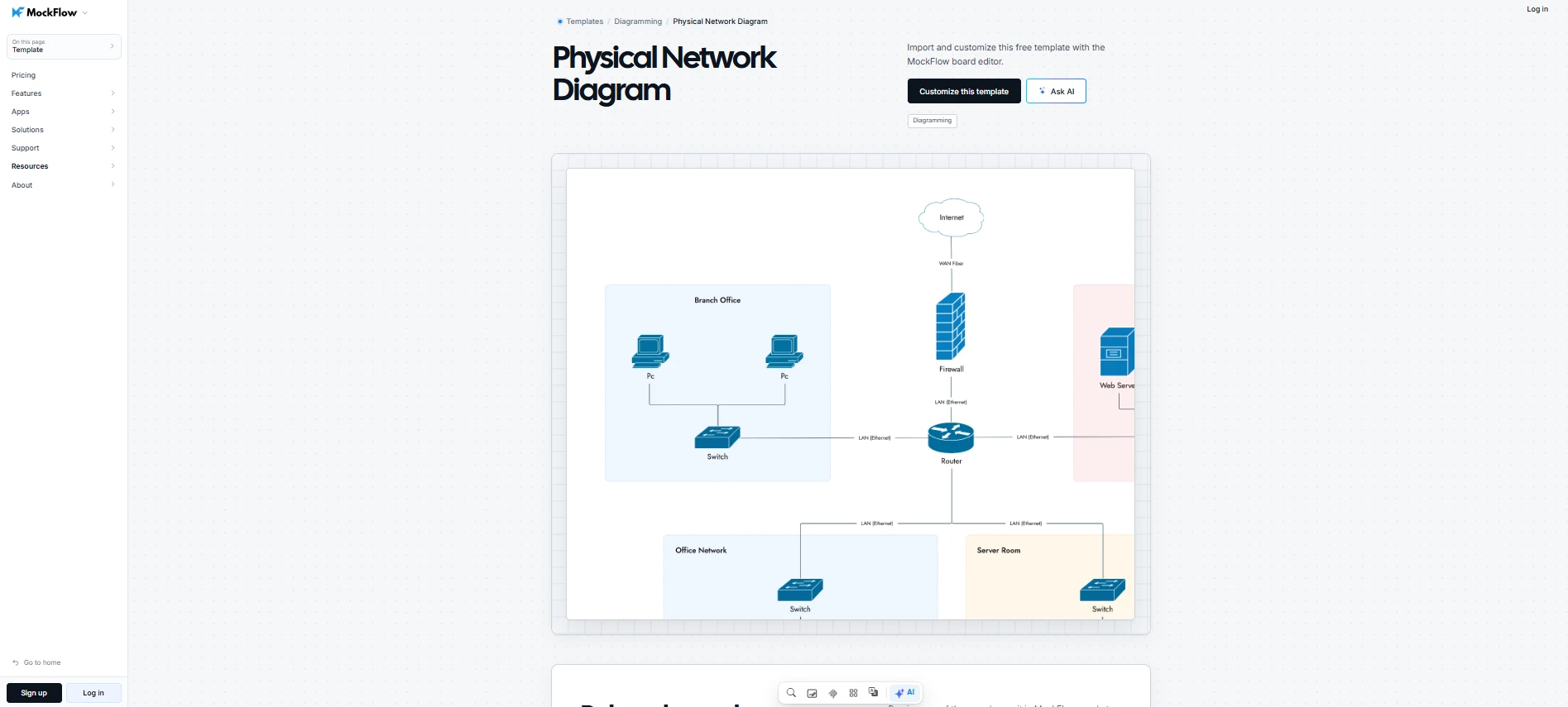
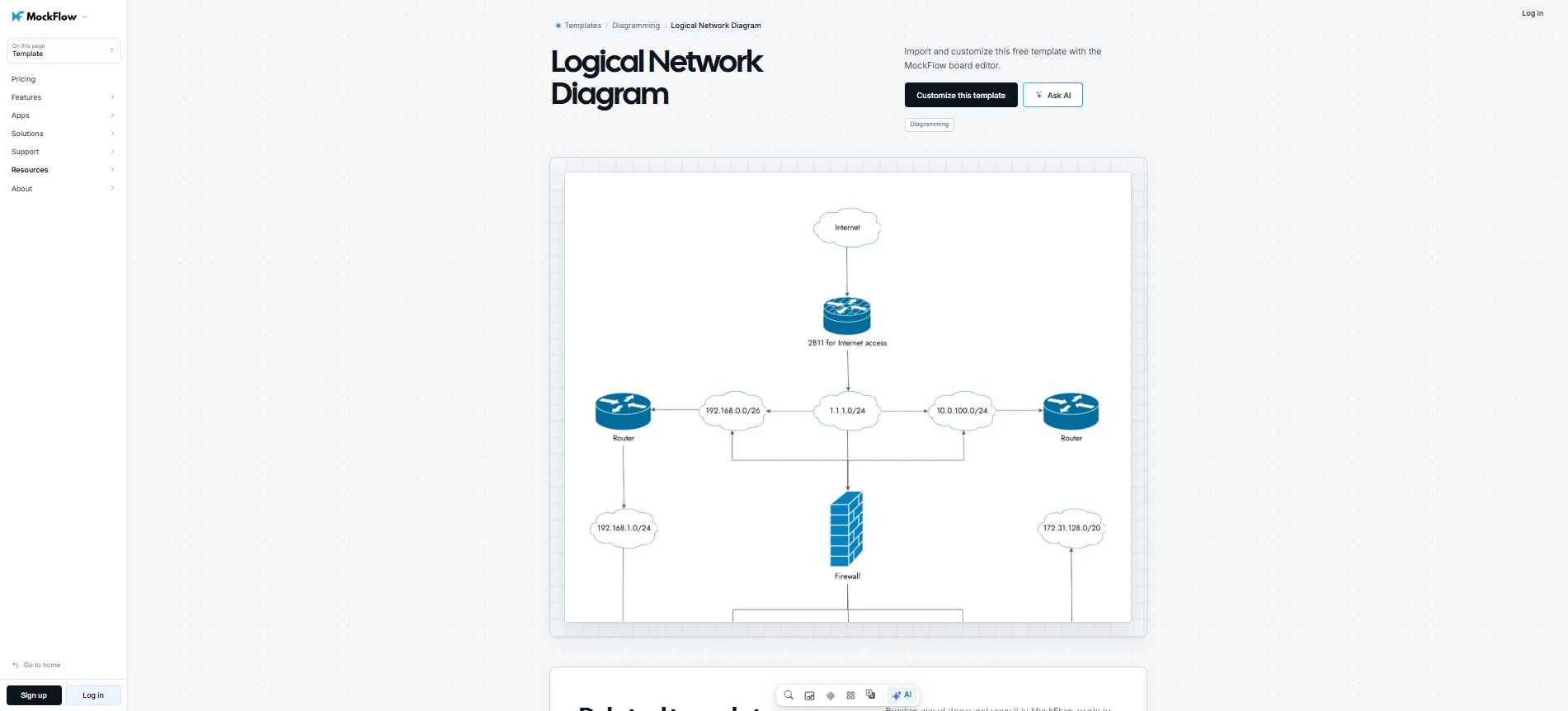
Physical and logical network diagrams can represent the same infrastructure from different perspectives.
- Physical network diagram: Shows where equipment is installed and how cables connect devices. For example, a diagram may identify switches in a server rack and their connections to office workstations.
Customize physical network diagram template
- Logical network diagram: Shows how network segments communicate. For example, employee and guest VLANs may connect through a Layer 3 switch while remaining on separate subnets.
Customize this logical network diagram template
For a complex environment, organize the network across linked views and keep the overview focused on the main network path. Use separate pages or tabs for zones, devices, and service inventories so readers can open a detailed view only when they need it.
4. Cloud network architecture diagram
A cloud network architecture diagram maps how cloud resources connect and exchange data. For example, an Azure network may contain separate subnets for application servers and databases, with a load balancer managing incoming traffic. Firewalls control access between network segments.
Flexera’s 2025 State of the Cloud Report found that 70% of respondents used at least one public and one private cloud. If your infrastructure spans both, a diagram can help your team see where those environments connect and how traffic moves between them.
MockFlow provides several ways to represent cloud network infrastructure:
- Generate an initial design: With MockFlow's Cloud Architecture Generator, you can describe your cloud infrastructure in plain text. Teams can generate an editable diagram using provider-specific icons for AWS, Azure, or GCP, reducing the need to place every component manually.
- Adapt an existing Azure layout: MockFlow's Azure Cloud Architecture Example illustrates a hub-and-spoke design with Azure Firewall and VPN connectivity. You can use the existing layout to understand how shared network services connect to individual workloads before adapting the diagram.
- Map hybrid cloud connectivity: The Google Cloud and On-Premise Architecture Template provides a layout for representing cloud and local infrastructure together. Customize the connections to document how on-premises systems communicate with cloud resources.
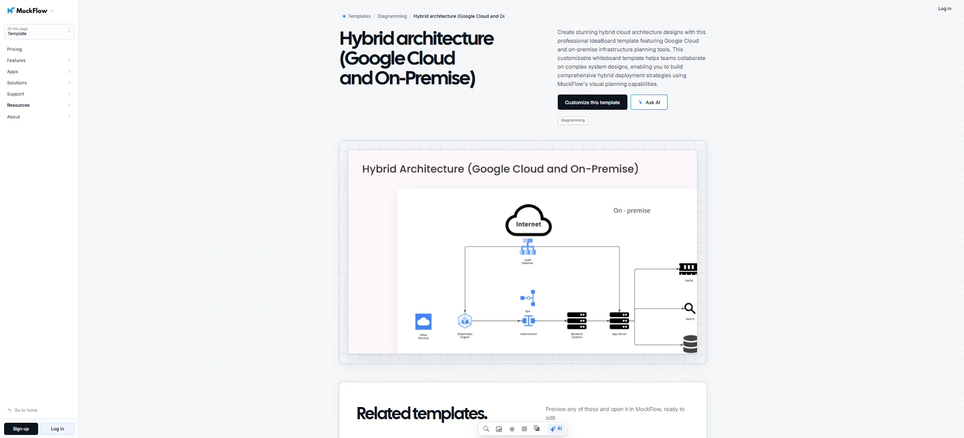
Customize this hybrid architecture (Google Cloud and on-premise) template
5. VLAN and network security diagram
A VLAN or network security diagram shows how network segments are separated and how traffic moves between them. It can map employee, guest, and server VLANs alongside routing devices, firewalls, and a DMZ for public-facing services.
A Security Network Diagram Template can help map these zones and access paths, making it easier to review firewall policies and spot connections that may not follow the intended design.
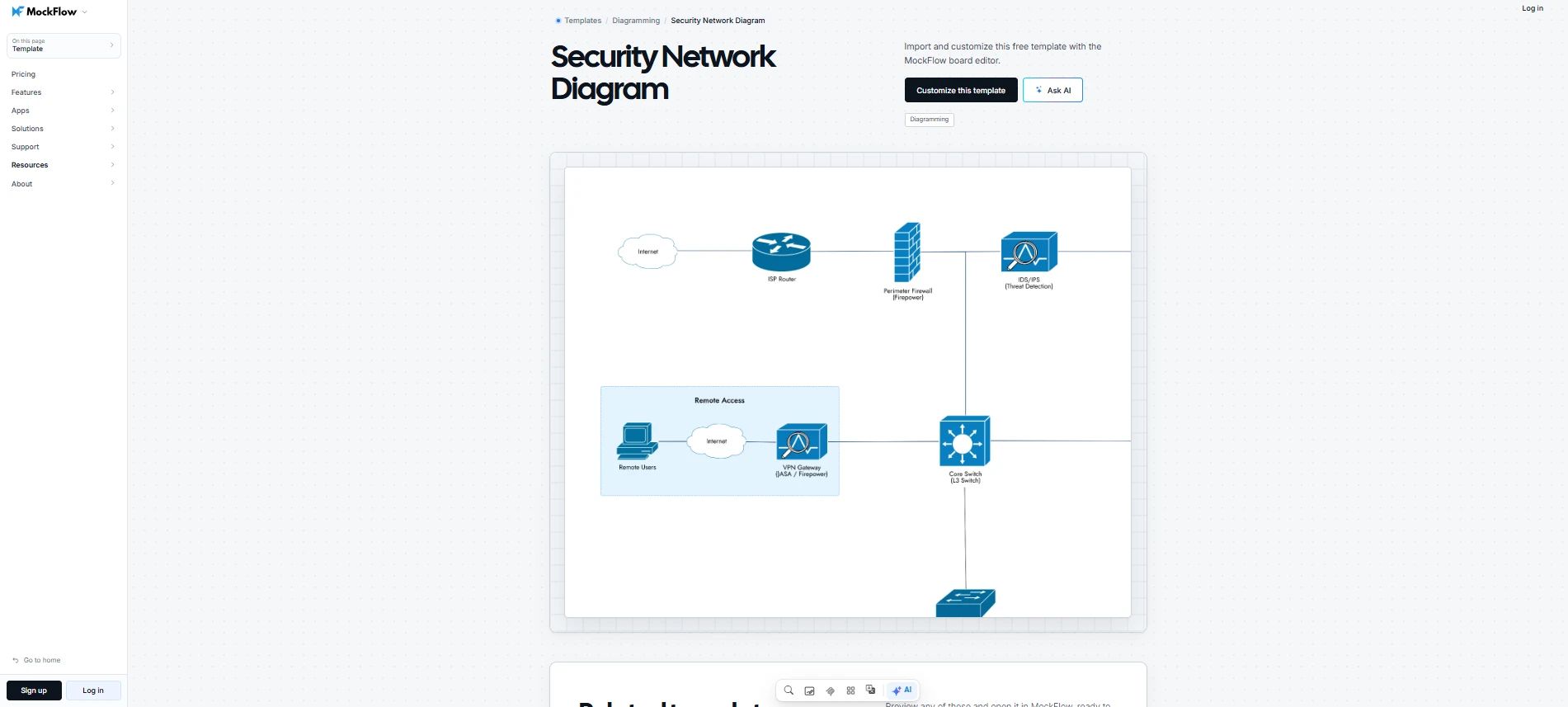
Customize this security network diagram template
6. Enterprise and WAN network diagram
An enterprise network diagram shows how locations connect through WAN links or site-to-site VPNs, and how they reach shared infrastructure.
It can capture:
- Site connectivity: WAN links and VPNs between headquarters and branch offices.
- Internal network structure: Core, distribution, and access layers at each location.
- Shared infrastructure: Connections to centralized servers and cloud services.
A WAN Network Diagram Template helps map these connections so teams can trace dependencies between sites and plan network expansion.
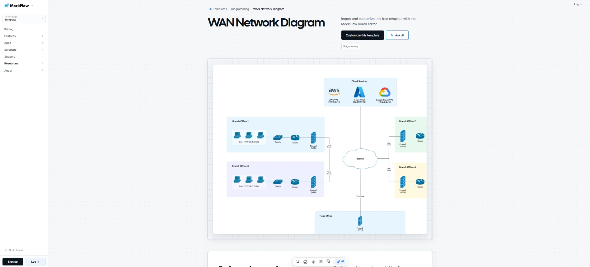
Customize this WAN network diagram template
Related Read: Workflow Diagram: Types, Examples, Templates & How to Create
How to create a network architecture diagram using MockFlow
MockFlow is a visual planning and brainstorming platform that combines diagramming and collaborative whiteboarding on a shared canvas. You can use its AI assistant, Mida, to generate network architecture diagrams from text prompts, then customize the connections and review the design with your team.
Here's how to create a network architecture diagram using MockFlow.
Step 1. Define the network scope and components
Open a MockFlow board, select Frames from the toolbar, and choose Diagram.
The Diagram frame provides an editable workspace where your network architecture can sit alongside technical documentation or application wireframes.
When documenting an existing network, trace uplinks before mapping routed neighbors, then identify subnets and Layer 2 connections. Where you have permission and command-line access, device neighbor tables and MAC address tables can help verify links and flag possible unmanaged switches.
Step 2. Open MockFlow and set up a diagram frame
Mida understands written instructions and turns them into editable diagrams. You can also ask Mida to modify existing board content when requirements change.
To generate a Cisco network diagram:
- Select the Diagram frame and click AI.
- Choose Generate diagram and select Cisco network architecture.
- Describe your network and generate the diagram.
For example:
“Generate an enterprise network diagram with core routers, distribution switches, Cisco firewalls, three VLANs, and WAN links to two branches. Label security zones.”
For complex designs, Concept Builders guide architecture development through multiple interactions. You can also adapt architecture templates to avoid rebuilding established layouts.
Step 3. Customize the network architecture
Use MockFlow's searchable shape libraries to locate networking components.
- Add devices and adjust their connections.
- Use Flow packs and containers to organize network segments.
- Label subnets and VLANs to identify communication paths.
- Link related diagrams to separate complex infrastructure layers.
Step 4. Review the architecture collaboratively
Verify connections against your network configuration. MockFlow's real-time collaboration and commenting tools let engineers discuss changes directly on the diagram using text, voice, or video feedback.
During review meetings, you can open the diagram on the Google Meet stage for collaborative editing. For ongoing discussions, adding the board to Microsoft Teams keeps the architecture accessible within your team's channel.
Step 5. Connect the diagram to technical workflows
Once the network design is reviewed, make the diagram accessible wherever your team manages infrastructure changes.
- Confluence: Embed your MockFlow board in Confluence alongside network configuration details and runbooks. Engineers can refer to the architecture while following maintenance procedures without searching for a separate diagram.
- Jira: Link the MockFlow board to a Jira issue when planning network upgrades. This lets engineers compare proposed changes against the architecture while working on the infrastructure ticket.
Step 6. Export and maintain the network diagram
Export the finalized diagram as PNG or SVG when you need a static copy for documentation. If the network changes frequently, embedding the MockFlow board in an internal portal gives your team access to the maintained diagram without repeatedly replacing exported images.
For teams working with AI development tools, MockFlow MCP lets engineers generate architecture diagrams through Claude or Cursor. This is useful when network requirements are already being developed in an AI-assisted workflow, allowing engineers to create a visual design from the same working context.
Tip: Treat documentation as part of the change process by making diagram updates part of change management, with the update completed before a network change ticket is closed. A short recurring review can also catch changes that bypassed the usual workflow, keeping the diagram useful for troubleshooting and onboarding.
Related Read: How to Draw an Architecture Diagram: Step by Step
Conclusion
A network architecture diagram is most useful when it reflects how your infrastructure actually works and gives your team a reliable reference for future changes. The right diagram structure depends on your network and the technical details you need to communicate.
MockFlow makes creating and maintaining network diagrams part of your team's existing workflow. You can build on established architecture patterns, work through complex designs with AI assistance, and maintain a shared reference as your infrastructure evolves.
Whether you're planning a new network or documenting an existing one, MockFlow gives your team a flexible environment to develop the design and keep everyone aligned.
Get started with MockFlow and create a network architecture diagram suited to your infrastructure.
FAQs
1. What is the difference between a network architecture diagram and a network topology diagram?
A network architecture diagram represents the overall network design, including its infrastructure and communication paths. A network topology diagram focuses specifically on how devices are connected and arranged. Topology is one part of network architecture and helps explain the connection patterns used within the network.
2. What are the main components of a network architecture diagram?
A network architecture diagram typically includes routers, switches, firewalls, servers, and endpoints. It also represents the connections between devices and shows how the network is divided into segments. Depending on the infrastructure, the diagram may include load balancers, wireless access points, cloud resources, and security boundaries.
3. What is the difference between a logical and physical network diagram?
A physical network diagram shows the actual networking hardware and how devices connect through cables or other physical links. A logical network diagram represents how data communicates across subnets and VLANs, regardless of equipment location. Physical diagrams are useful for hardware maintenance, while logical diagrams support routing analysis and network configuration reviews.
4. What is a cloud network architecture diagram?
A cloud network architecture diagram represents how networking resources are organized and connected within cloud environments such as AWS, Azure, or GCP. It typically shows virtual networks, subnets, gateways, and cloud services. The diagram helps engineers understand communication between cloud resources and how traffic moves through the infrastructure.
5. How do you create a network architecture diagram?
Start by identifying the network environment and the components you need to represent. Choose a physical or logical layout, then arrange the devices and connect them according to the intended network design. Add relevant technical labels and verify the connections before sharing the diagram. Tools like MockFlow can help generate an initial layout using AI and refine it through an editable diagram workspace.
6. What is the best format for a network architecture diagram?
The best format depends on how the diagram will be used. PNG works well for inserting diagrams into presentations or documentation, while SVG provides scalable graphics that remain sharp when resized. For networks that change frequently, an editable diagram format is preferable because engineers can update components and connections without recreating the diagram.

8 Group Brainstorming Techniques for Remote Collaboration in 2026
Introduction Group brainstorming is one of those activities that seems simple at first but can turn into something really...

5 Asynchronous Collaboration Strategies for Modern Remote Teams
Introduction When our teams work across different time zones, schedules rarely line up perfectly. Someone is starting their day...

Workflow Diagram: Types, Examples, Templates & How to Create
Introduction When we sit down to map a process, it usually starts off simple. A few steps, a couple of decisions, nothing...
